Gaskets for Flanged Connnections
Gaskets for flanged connections
What is a Flange Gasket?
Flange gaskets are used to create a static seal between two flanges faces, at various operating conditions, with varied pressure and temperature ratings. A gaskets fills the microscopic spaces and irregularities of the flange faces, and then it forms a seal that is designed to keep liquids and gases. Correct installation of damage-free gaskets and demage-free flange faces is a requirement for a leak-free flange connection.
Types of gaskets
Materials for gaskets can be divided into three main categories:
- NON-METALLIC TYPES
- SEMI-METALLIC TYPES
- METALLIC TYPES
NON-METALLIC GASKETS
NON-METALLIC GASKETS are usually composite sheet materials are used with flat-face and raised-face flanges in low Pressure Class applications. Non-metallic gaskets are manufactured from arimid fiber, glass fiber, elastomer, Teflon® (PTFE), graphite etc.. Full-face gasket types are suitable for use with flat-face flanges. Flat-ring gasket types are suitable for use with raised face flanges.
ASME B16.21 covers types, sizes, materials, dimensions, dimensional tolerances, and markings for non-metallic flat gaskets.
SEMI-METALLIC GASKETS
SEMI-METALLIC GASKETS are composites of metal and non-metallic materials. The metal is intended to offer strength and resiliency, while the non-metallic portion provides conformability and sealability. Often used semi-metallic gaskets are spiral wound and camprofile, and a variety of metal-reinforced graphite gaskets.
Semi-metallic are designed for almost all operating conditions and high-temperature and pressure applications, and are us
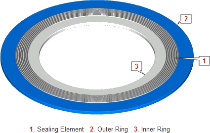
TYPICAL SPIRAL WOUND GASKET
METALLIC GASKETS
METALLIC GASKETS are fabricated from one or a combination of metals to the desired shape and size. Often used metallic gaskets are ring-type-joint gaskets (RTJ). They are always applied to special, accompanying flanges which ensure good, reliable sealing with the correct choice of profiles and material.
Ring Type Joint gaskets are designed to seal by “initial line contact” or wedging action between the mating flange and the gasket. By applying pressure on the seal interface through bolt force, the “softer” metal of the gasket flows into the microfine structure of the harder flange material, and creating a very tight and efficient seal.ASME B16.20 covers materials, dimensions, dimensional tolerances, and markings for metallic and semi-metallic gaskets.
Often used Semi-Metallic gaskets
Here below you will find a short description of a number of semi-metallic gaskets, which are largely used.
Spiral Wound gaskets
The concept of spiral wound gasket construction was originated by Flexitallic in 1912, inaugurating the beginning of a new era in safe, effective sealing. The primary purpose for this development was the increasingly severe temperatures and pressures used by U.S. refinery operators in the first half of the century.
The necessity for a gasket to have the ability to recover cannot be over emphasized. The effects of pressure and temperature fluctuations, the temperature differential across the flange face, together with bolt stress relaxation and creep, demand a gasket with adequate flexibility and recovery to maintain a seal even under these varying service conditions. The Spiral Wound Gasket is the precision engineered solution to such problems, meeting the most exacting conditions of both temperature and pressure in flanged joints and similar assemblies and against virtually every known corrosive and toxic media.The spiral wound gasket meets the most exacting conditions of both temperature and pressure in flanged joints and similar assemblies and against every known corrosive and toxic media.
The spiral wound gasket depends upon the mechanical characteristics of a formed metal spiral strip, rather than the compressive virtues of more traditional gasket materials. This makes it particularly suitable for low or fluctuating bolt loads. The sealing strips, or fillers, are usually graphite, although other materials such as Teflon® (PTFE) may be used, the windings are always stainless steel. For this type of gasket to work the spiral must not be over compressed, hence one of two types of compression control is usually used.
The completed gasket is fitted into a steel ring of specific thickness. When the gasket is fitted into a flange and the bolt load is applied, flange closure is governed by the outer steel ring of the gasket. To further improve the pressure rating of the spiral wound gasket, a steel ring may be added to the inside. This gives an additional compression limiting stop and provides a heat and corrosion barrier protecting gasket windings and preventing flange erosion. It is customary to select inner ring material to be the same as the metal winding.
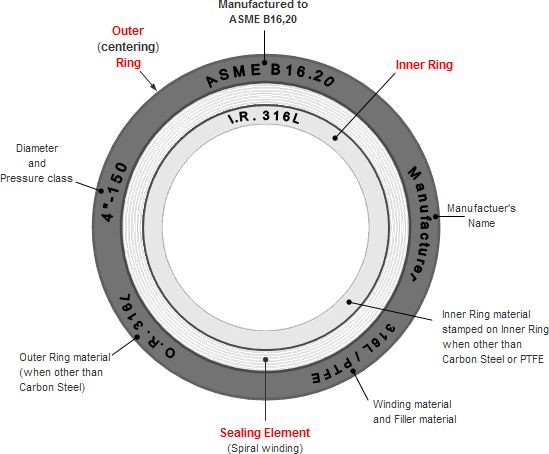
ASME B16.20 which covers spiral wound gaskets requires the use of solid metal inner rings in: Pressure Class 900, nominal pipe sizes 24 and larger, Pressure Class 1500 from nominal pipe sizes 12 and larger, Pressure Class 2500 from nominal pipe sizes 4 and larger and all PTFE filled gaskets. In the same standard is also described how a spiral wound gasket should be characterized, below you will find a image on it.
Marking Spiral Wound Gaskets
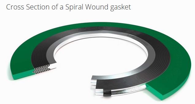
Cross Section of a Spiral Wound gasket
Camprofile gaskets
Camprofile or “Grooved” gaskets have proven themselves in all industrial applications. Camprofile gaskets are found in industrial power plants and in the primary circuits in nuclear installations. Used either between flanges or in Heat Exchanger units in nuclear applications. The Petro and chemical industry benefit too, as the gaskets are used in applications where high pressures and temperatures are maintained and consequently high bolt loads need to be controlled.
Camprofile Gasket
Camprofile gaskets consist of a metal core (generally Stainless Steel) with concentric grooves on either side with sealing materials. The sealing layers (depending on the service duty) can be Graphite, PTFE (Teflon®), CAF or Metal (e.g. Aluminium or Silver). Camprofile`s can be used without sealing layers to provide an excellent seal but there is a risk of flange surface damage – especially at high seating loads. The sealing layers protect the flange surfaces from damage in addition to providing an effective seal.
Metal Jacketed gaskets
Metal Jacketed gaskets, as the name suggests, are comprised of a metallic outer shell with either a metallic or non-metallic filler. The filler material gives the gasket resilience, while the metal jacket protects the filler and resists pressures, temperatures and corrosion.
They are traditionally used for Heat Exchanger applications, pumps and Valves, however the resilience and recovery properties of these gaskets are limited. Metal Jacketed gaskets require smooth flange surface finishes, high bolt loads and flange flatness in order to seal effectively.
There are many different styles of jacketed gaskets available. In the main Menu “Gaskets” you will find a link to the dimensions of double jacketed flange gaskets. In that type the filler material is completely enclosed by a two piece metal jacket, which covers both the inside and outside diameters and both contact surfaces.
Metallic gaskets for RTJ Flanges
The ring type joint was initially developed for use in the petroleum industry, where high pressure/temperature applicationsnecessitated the need for a high integrity seal. They are mainly used in the oil field on drilling and completion equipment. Ring type joints are also commonly used on Valves and pipework assemblies, along with some high integrity pressure vessel joints.
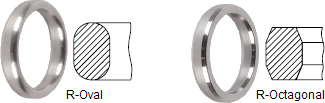
Most applied type is style R ring that is machined to tight manufacturing tolerances in accordance with the relevant standards, to ensure correct installation in standard API 6B and ASME B16.5 Ring Type Flanges.
Oval and Octagonal RTJ`s with the same ring size designation can be interchangeable in standard flanges with flat bottomed ring grooves. For the old style round bottomed grooves Oval RTJ`s only can be used. Materials of construction are selected to match the flange material and to be resistant to the corrosive and erosive media. In addition, the material hardness of the RTJ`s is less than the hardness of the flanges to ensure the RTJ is deformed and not the flanges when assembled. Non-standard size RTJ`s are specifically designed to be installed in flanges designed around a specific application rather than a standard flange.
- Metallic Gasket RTJ Type R
- Metallic Gasket RTJ Type RX
- Metallic Gasket RTJ Type BX
TYPICAL APPLICATION
Oval and Octagonal RTJ`s are designed to seal pressures of up to 6,250 psi in accordance with ASME B16.20 and up to 5,000 psi in accordance with API 6A pressure ratings. Typical high pressure and temperature applications where these gaskets are used include Valve and pipe-work assemblies in oil field drilling and refining applications. In addition, these gaskets are installed in high pressure vessels and pumps.
HOW THEY WORK
Under axial compressive load, ring type joints plastically deform and flow into the irregularities of the flange groove. Since the load bearing area of the ring type joint is relatively small, very high surface stresses result between the sealing faces of the ring type joint and the groove. These stresses are further increased on the Style RX and BX rings which allows very high internal pressures to be sealed. Since ring type joints are solid metal, their recovery characteristics are poor. The seal is maintained by the action of axial load upon the gasket.
RE-USE
Ring type joints are designed to have a limited amount of positive interference, which ensures that the ring type joint seats correctly into the groove on compression. Their reuse is not recommended for two reasons:
- The initial seating of the gasket will be impaired
- When the gasket is plastically deformed, work hardening of the external metal surface occurs. This may result in permanent damage to the groove.
HARDNESS OF MATERIALS
On compression of the flange assembly, it is imperative that the ring type joint be significantly softer than the flange groove so that the gasket plastically deforms and not the groove. The use of harder ring type joints can result in flange groove damage. For this reason, ring type joints are supplied with the following maximum hardness values:
| Maximum Hardness | ||||
|
Material |
Wst No | Brinel (1) | HRB (2) | ID |
|
Soft Iron |
90 | 56 | D | |
|
Low Carbon Steel |
120 | 68 | S | |
|
4 - 6% Chrome |
130 | 72 | F5 | |
|
Type 304 |
1.4301 | 160 | 83 | S304 |
|
Type 316 |
1.4401 | 160 | 83 | S316 |
|
Type 347 |
1.4550 | 160 | 83 | S347 |
|
Type 410 |
1.4006 | 170 | 96 | S410 |
Notes:
- Measured with 3000 kg load except soft iron which is measured with 500 kg load.
- (Rockwell) measured with 100 kg load and 1/16in diameter ball.
PROTECTIVE COATING
In accordance with API Specifications, soft iron, low carbon steel, and other ferrous materials ring type joints are protected from corrosion with electroplated zinc or cadmium to a maximum thickness of 0.0005 in. Alternative material coatings can be supplied.